
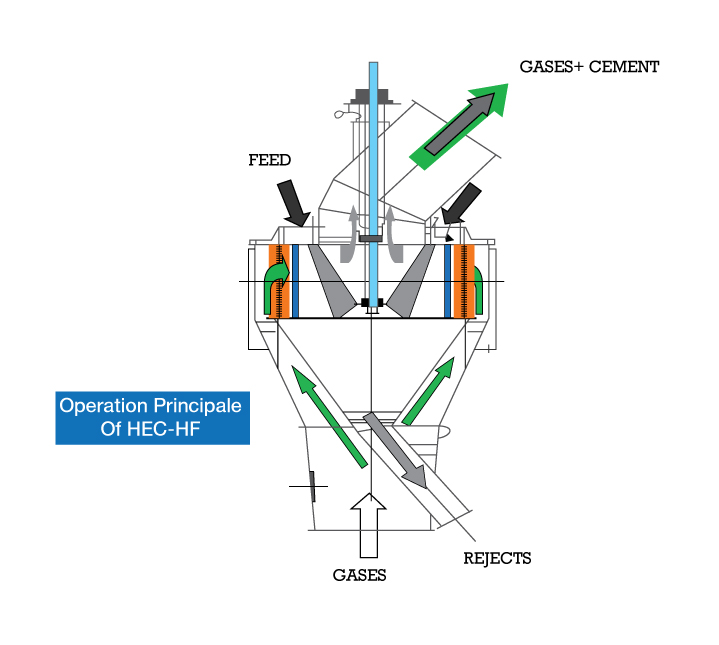
The 4th generation High Efficient Classifiers (HEC) is a fully automated control system that allows us to maintain strict quality control guidelines. Made of top-quality high wear-resistant materials like HARDOX 400, the classifier provides optimal protection against wear and tear. The HEC is capable of handling very high specific material loads. As a result of its turbo design, the HEC’s power consumption is very low. And finally, its unique turbine blade design increases the separation zone by five to ten times compared with other designs.
The flow of gas is rectified by way of the adjustable stator blades, which allows the tangential speed of the gas to be adapted to the turbine rotation speed so as to obtain only a radial speed of the fluid of the turbine.
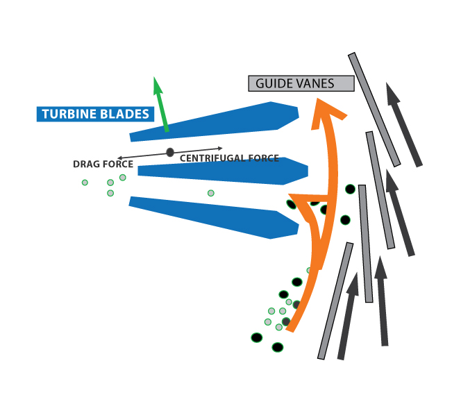
Therefore, a drag speed which is directly centripetal and opposing the centrifugal force is obtained which limits wear of the blades by the absence of particle impact on the latter. A closing which is adapted to the blades causes pressure loss which is favorable to the proper homogeneity of the speed profiles upon inlet of the turbine on its periphery and its height.
Cutting precision, which is characterized by weak imperfection or by a high slope of the (separation curve), is reached by using a patented turbine blade profile. The blades are designed in a way so as, regardless of the position in the passage between two turbine blades, the cutting diameter is the same, which means that the centrifugal and drag forces are equal for a given diameter of the particle. Since the closer one is to the center of the turbine, the more the centrifugal force decreases, the drag force must be decreased. This is obtained by slowing down the radial speed by widening the passage when moving towards the turbine axis. So the separation area is not limited to the rotor periphery but extends in all the passages between the turbine blades. This is essential to ensure great cutting quality for practical conditions far from ideal operating conditions, such as turbulence of running speeds which are not even upon turbine inlet.
For better evacuation of the fine particles with the gas and to rectify the rotational flow of the outlet gas, a vortex system made up of radial blades is added to the center of the turbine.